- 您现在的位置:买卖IC网 > Sheet目录337 > LT3477EFE#PBF (Linear Technology)IC LED DRVR HP CONS CURR 20TSSOP
LT3477
APPLICATIONS INFORMATION
PWM Dimming
For LED applications where a wide dimming range is
required, two competing methods are available: analog
dimming and PWM dimming. The easiest method is to
simply vary the DC current through the LED —analog
dimming—but changing LED current also changes its
chromaticity, undesirable in many applications. The bet-
ter method is PWM dimming, which switches the LED
on and off, using the duty cycle to control the average
current. PWM dimming offers several advantages over
analog dimming and is the method preferred by LED
manufacturers. By modulating the duty cycle of the PWM
signal, the average LED current changes proportionally
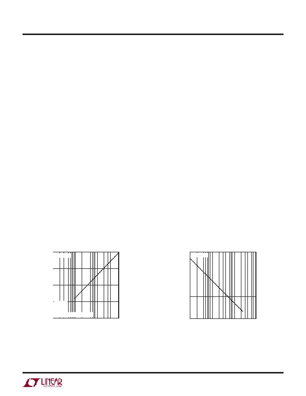
as illustrated in Figure 5. The chromaticity of the LEDs
remains unchanged in this scheme since the LED current is
either zero or at programmed current. Another advantage
of PWM dimming over analog dimming is that a wider
dimming range is possible.
The LT3477 is a DC/DC converter that is ideally suited for
LED applications. For the LT3477, analog dimming offers
a dimming ratio of about 10:1; whereas, PWM dimming
with the addition of a few external components results in
a wider dimming range of 500:1. The technique requires a
PWM logic signal applied to the gate of both NMOS (refer
to Figure 7). When the PWM signal is taken high the part
runs in normal operation and I LED = 100mV/R SENSE runs
through the LEDs. When the PWM input is taken low, the
LEDs are disconnected and turn off. This unique external
circuitry produces a fast rise time for the LED current,
resulting in a wide dimming range of 500:1 at a PWM
frequency of 100Hz.
The LED current can be controlled by feeding a PWM signal
with a broad range of frequencies. Dimming below 80Hz is
possible, but not desirable, due to perceptible ?ashing of
LEDs at lower PWM frequencies. The LED current can be
controlled at higher frequencies, but the dimming range
decreases with increasing PWM frequency, as seen in
Figure 6.
PWM dimming can be used in boost (shown in Figure 7), buck
mode (shown in Figure 8) and buck-boost mode (shown
in Figure 9). For the typical boost topology, ef ?ciency ex-
ceeds 80%. Buck mode can be used to increase the power
handling capability for higher current LED applications. A
buck-boost LED driver works best in applications where
the input voltage ?uctuates to higher or lower than the
total LED voltage drop.
In high temperature applications, the leakage of the
Schottky diode D1 increases, which in turn, discharges the
output capacitor during the PWM off time. This results in
a smaller effective LED dimming ratio. Consequently, the
dimming range decreases to about 200:1 at 85°C.
100
R T = 6.81k
1000
R T = 6.81k
10
100
1
10
0.1
V IN = 5V
BOOST
4 LEDs
PWM FREQUENCY = 100Hz
0.01
0.1 1 10
100
1
0.1
1
10
100
PWM DUTY CYCLE (%)
3477 F05
PWM FREQUENCY (kHz)
3477 F06
Figure 5. LED Current vs PWM Duty Cycle
Figure 6. Dimming Range vs PWM Frequency
Wide Dimming Range (500:1)
3477fc
11
发布紧急采购,3分钟左右您将得到回复。
相关PDF资料
LT3478IFE#PBF
IC LED DRVR HP CONS CURR 16TSSOP
LT3486EFE#PBF
IC LED DRVR WHITE BCKLGT 16TSSOP
LT3491EDC#TRMPBF
IC LED DRIVER WHITE BCKLGT 6-DFN
LT3492IFE#TRPBF
IC LED DVR HP CONST CURR 28TSSOP
LT3496IUFD#PBF
IC LED DRVR WHT/RGB BCKLT 28-QFN
LT3497EDDB#TRMPBF
IC LED DRIVR WHITE BCKLGT 10-DFN
LT3498EDDB#TRPBF
IC LED DRVR WT/OLED BCKLGT 12DFN
LT3517HUF#PBF
IC LED DRIVER AUTOMOTIVE 16-QFN
相关代理商/技术参数
LT3477EFE#TR
制造商:Linear Technology 功能描述:LED DRVR 4Segment 3.3V/5V/9V/12V/15V/18V/24V 20-Pin TSSOP EP T/R
LT3477EFE#TRPBF
功能描述:IC LED DRVR HP CONS CURR 20TSSOP RoHS:是 类别:集成电路 (IC) >> PMIC - LED 驱动器 系列:- 标准包装:6,000 系列:- 恒定电流:- 恒定电压:- 拓扑:开路漏极,PWM 输出数:4 内部驱动器:是 类型 - 主要:LED 闪烁器 类型 - 次要:- 频率:400kHz 电源电压:2.3 V ~ 5.5 V 输出电压:- 安装类型:表面贴装 封装/外壳:8-VFDFN 裸露焊盘 供应商设备封装:8-HVSON 包装:带卷 (TR) 工作温度:-40°C ~ 85°C 其它名称:935286881118PCA9553TK/02-TPCA9553TK/02-T-ND
LT3477EFEPBF
制造商:Linear Technology 功能描述:LED Driver 4-Seg 3.3/5/9/../24V TSSOP20
LT3477EUF
制造商:Linear Technology 功能描述:LED DRVR 4Segment 3.3V/5V/9V/12V/15V/18V/24V 20-Pin QFN EP
LT3477EUF#PBF
功能描述:IC LED DRVR HP CONST CURR 20-QFN RoHS:是 类别:集成电路 (IC) >> PMIC - LED 驱动器 系列:- 标准包装:60 系列:- 恒定电流:- 恒定电压:- 拓扑:线性(LDO),PWM,升压(升压) 输出数:8 内部驱动器:是 类型 - 主要:背光 类型 - 次要:RGB,白色 LED 频率:500kHz ~ 1.5MHz 电源电压:4.75 V ~ 26 V 输出电压:45V 安装类型:* 封装/外壳:* 供应商设备封装:* 包装:* 工作温度:-40°C ~ 85°C
LT3477EUF#PBF
制造商:Linear Technology 功能描述:IC, LED DRVR, QFN20
LT3477EUF#TRPBF
功能描述:IC LED DRVR HP CONST CURR 20-QFN RoHS:是 类别:集成电路 (IC) >> PMIC - LED 驱动器 系列:- 标准包装:6,000 系列:- 恒定电流:- 恒定电压:- 拓扑:开路漏极,PWM 输出数:4 内部驱动器:是 类型 - 主要:LED 闪烁器 类型 - 次要:- 频率:400kHz 电源电压:2.3 V ~ 5.5 V 输出电压:- 安装类型:表面贴装 封装/外壳:8-VFDFN 裸露焊盘 供应商设备封装:8-HVSON 包装:带卷 (TR) 工作温度:-40°C ~ 85°C 其它名称:935286881118PCA9553TK/02-TPCA9553TK/02-T-ND
LT3477IFE
制造商:LINER 制造商全称:Linear Technology 功能描述:3A, DC/DC Converter with Dual Rail-to-Rail Current Sense
